Tal Minear
Mechanical Engineer, Product Designer, & Project Manager
Design Portfolio
Click an image to learn more about the project.

Step Light

IP65 Outdoor Light
Drawer Slide Handlebar
Cryocooler Controller
Electronic Lock

Caltech MechE Capstone
Nano-Tensegrity-Lattices

Caltech Construction


About
I'm a Mechanical Engineer with a degree from Caltech and experience in the Industrial & Aerospace fields. R&D engineering is where I thrive, especially in the production of proof-of-concept designs and the evolution of those designs to mass production. I'm comfortable leading projects from start to finish, driving schedules, managing budgets, and overseeing design requirements. I love hands-on prototyping and testing, and I enjoy working in a fast paced environment with a cross-functional team and mentoring other engineers. When not at work, I can be found making fiction podcasts, reading fantasy novels, or painting jellyfish.
Handlebar for Locking Drawer Slides
The goal of this project was to design a rotating handlebar compatible with Accuride locking slides that would allow the opening of a drawer with one hand. I designed and prototyped the initial sample and assisted in the patent application for the system.

Design breakdown.
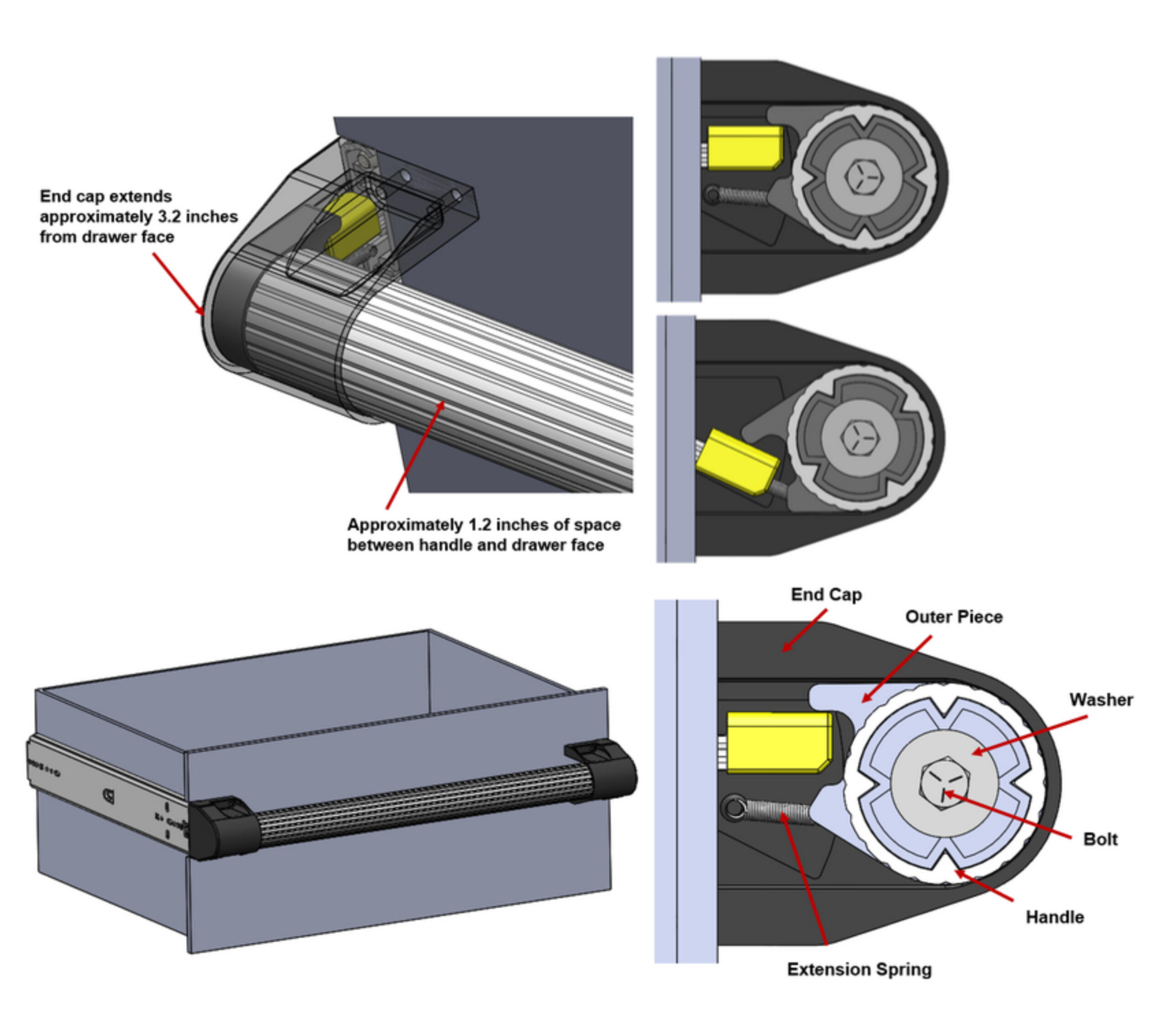
This handlebar was designed for use in ambulances, fire trucks, and other moving vehicles which required drawers to lock shut but be opened with one hand. Without this handlebar, two hands would be needed to push the drawer locks on each slide (in yellow, above) down and open the drawer. The handle attaches to the front of the drawer, and by rotating it, a mechanism to push the locks down is also rotated.Due to its use in vehicles, this handlebar could not stick very far out - but had to provide enough space to rotate the bar. This was the biggest challenge of the project. We did a lot of user testing on our initial prototypes to ensure that people of all hand sizes had no trouble opening the drawer.Parts were designed in Solidworks and prototyped using an SLA printer (and off the shelf parts, where possible). I led the development of this assembly, and worked with the company's patent lawyer in filing for a patent.
Electronic Lock for Drawer Slides
This project was an full product line of electronic locks compatible with Accuride drawer slides. I focused on the plastic housings for the electronic components, bringing them from initial prototype to mass production. This product line was called Senseon Access Control Electornics.

Senseon Housing & Full Assembly
Electronic Drawer Slide Lock
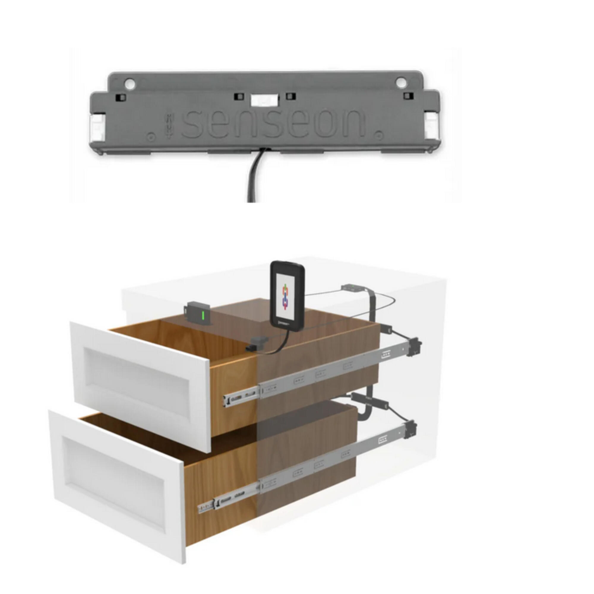
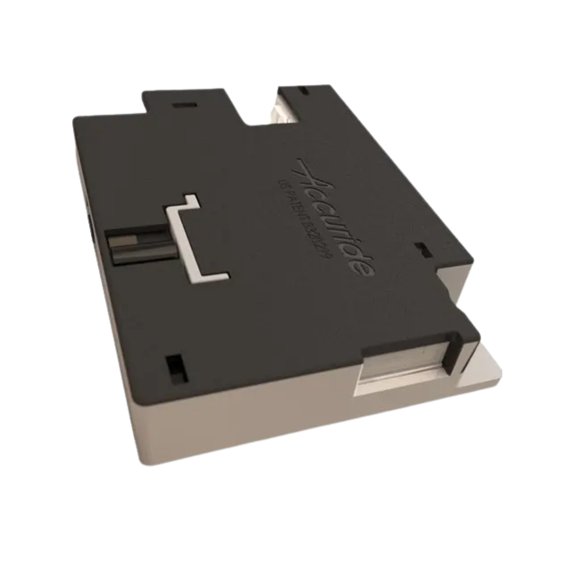
The full Senseon assembly consisted of 14 injection molded plastic housings for different parts of the system. These included RFID readers, slide locks and control hubs.I was brought onto this project after the housings had been designed, to provide DFMEA analysis and ready all parts for mass production injection molding. Many of these plastic housings were one piece with a plastic hinge that snapped closed. Ensuring the board fit and did not rattle in each enclosure was the major challenge of this initial mass production run.Bringing Senseon to mass production also required creating test fixtures for each board, so that the QA team could ensure system performance before shipping. I designed and produced each test fixture in conjuction with the electrical team.
Step Light Project
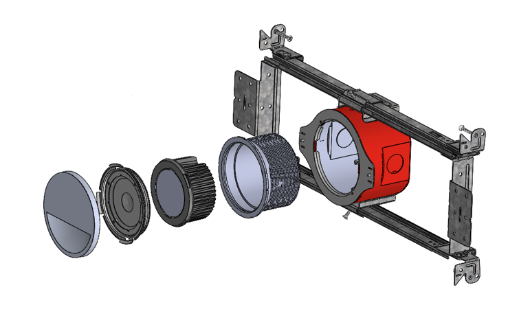
This project was the creation of a new product line of wall-mounted step lights, using an existing lighting module and housing. New parts created included trims, a collar, an optic cup, and an adapter plate. The system had to meet IP65 certification and be vandal proof. I led the initial design and testing of this product line and presented at the customer PDR and CDR.

Exploded view of full assembly. From left to right: trim, adapter plate, optic cup, lighting module, mounting collar, and housing.

Detail view of trim (die cast part)
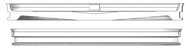
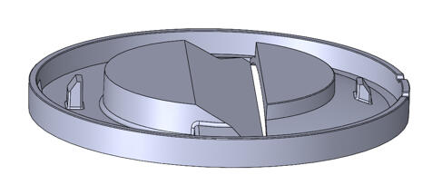
Section & detail view of optic cup (injection molded part)

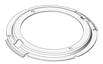
Detail view of adapter plate (sheet metal part)

Section view of housing, collar, lighting module, optic cup, and adapter plate in wall.

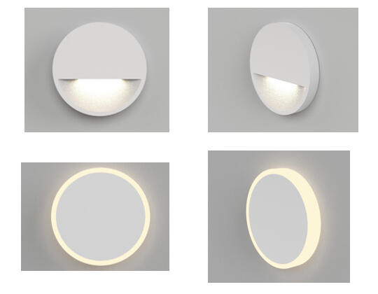
Views of fully installed step light.

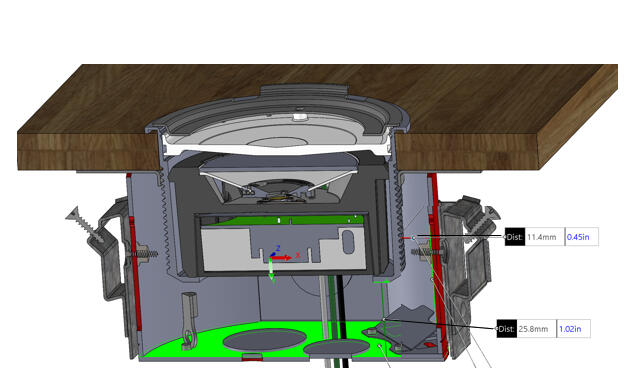
The step light project started as a simple set of requirements that turned out to be more complicated than they seemed.The most difficult part of this project was the customer’s request to use an existing DMF module for the step light project. They were using H-Series ceiling lights in their developments and wanted the convenience of utilizing the same module in their step lighting. Changing the use case of an already-designed module proved to be quite the challenge. We overcame this by clearly defining requirements of what could change and what couldn’t change, and designing the rest of the project’s parts around the module itself.The second biggest difficulty for this project was the IP65 waterproof requirement. DMF’s specialty is indoor ceiling downlights, which adhere to different standards than step lights (mounted in the wall, potentially outdoors). The module was initially designed as a ceiling light and did not meet IP65, which meant that the trim assembly around the light had to be watertight. We brought in engineers from DMF’s sister company (who have experience with outdoor lighting fixtures) to share their expertise and help define water testing that could be done in house. Ultimately, this difficulty was overcome with communication, iterative prototyping, and the design of new tests. We started out watering our prototypes with a garden hose, and finished with a specific test rig for the product.Beyond the IP certification, one of the biggest risks of this project (as it is for most lighting) was heat dissipation. Without proper contact between the module and trim, the LED will overheat. This risk was managed with thermal testing at each prototype stage, and modifications were made to the trim as needed to decrease heat. The team noted the RTI of all plastic parts to ensure the full assembly was well below temperature.These risks and challenges were kept in mind during the entire design process. All parts were made in Solidworks and initially prototyped using FDM and SLA printers. For thermal testing, aluminum prototypes were manufactured by an external CNC vendor.This product line consisted of die cast, injection molded, and sheet metal formed parts. Each part had difference tolerances, and some of them were made by different vendors. I led the coordination between Engineering and Manufacturing teams, and oversaw GD&T analysis to ensure the final assembly would fit together in mass production. I also led DFM analysis for each part at the same time, to ensure each part could be manufactured.
IP65 Outdoor Light Re-Design
This project was a redesign of an IP65 certified outdoor lighting fixture. The product was a wall mounted fixture with lighting modules pointing up and down. It was in stock and being sold when some customers reported that water was entering the fixture. I led the failure investigation of the product and the redesign efforts.

New Design for Snap Lenses.

New Design for Decorative Lenses.

Shower Testing Setup.

Pressure Testing Setup.
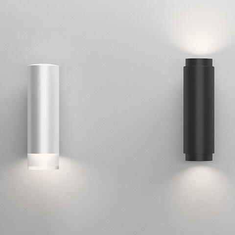
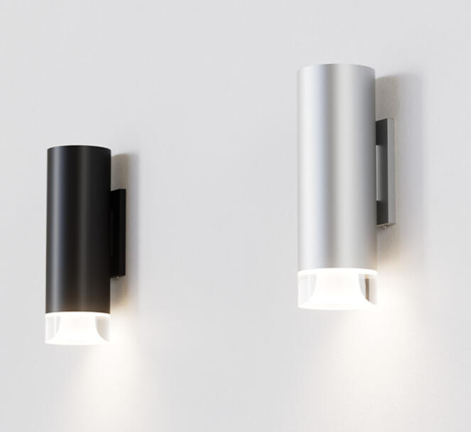
Final product installed.

Final product installed.
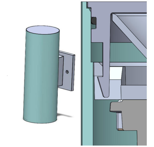
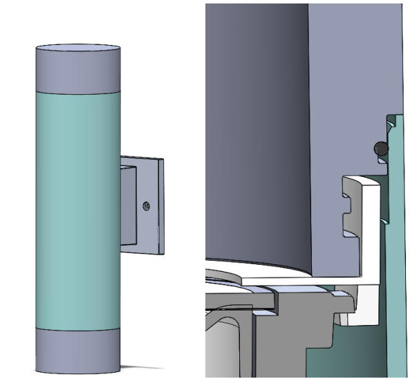
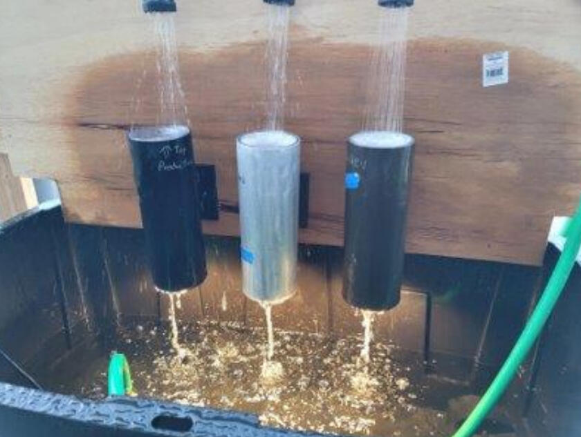
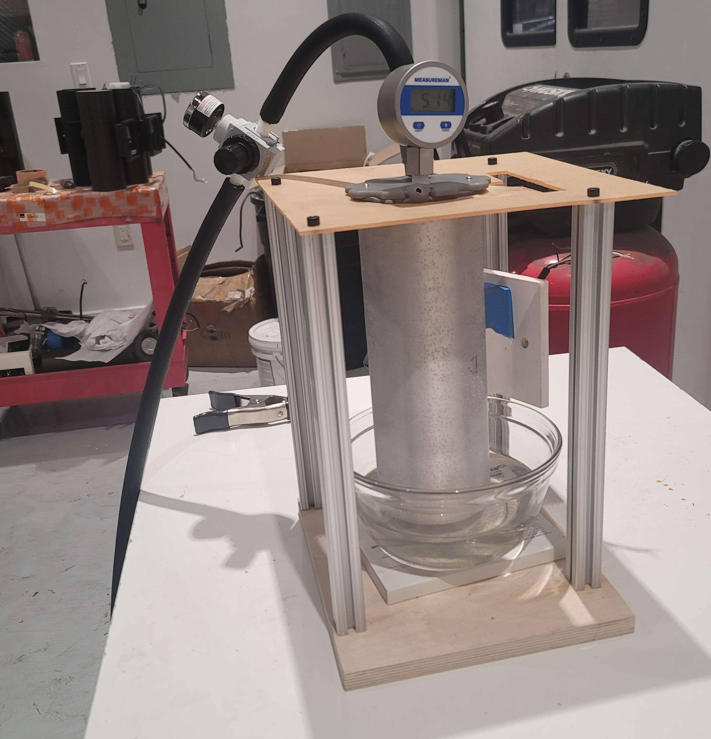

I was not part of the initial design for this product line, but was brought on to determine why units were failing and how to fix them. Product testing determined that this light was failing due to multiple reasons: the o-ring was not fully compressed, the assembly process was inconsistent, and the cylinder bodies were not within tolerance. Once the reasons for failure was determined, I led the project of fixing this product line.We had to follow two paths to solve this product. The first was a short-term solution that our production team could immediately implement. We created a process for caulking the top lenses, which required an additional laser cut sheet metal part to control caulk flow up and around the lens. I defined a new assembly process for the production team and trained the crew on the new process. Our production team implemented this short term solution while the engineering team made progress on a more permanent solution.The second path was a longer term solution that required modifying the tooling of the parts for the light to permanently fix the issue. The top lens was changed to correct the o-ring groove, and we worked with the vendor to better control their machining process for the cylinder body so that we could tighten the tolerances. This solution required equal design work as manufacturing work. I created our long term design using Solidworks and presented at PDR and CDR before tooling modifications were made.We also created rigs for testing units for both paths. Shower testing mimicked a unit's use case in the field (turned on and hot while cold water would rain on it). Pressure testing mimicked a unit's worst case pressure differential, and temperature cycling pushed the unit past its expected edge cases. A combination of these three tests allowed us to both determine why units were failing as well as validate our new designs.Leading two paths at the same time proved challenging, as many teams (Production, Sales, Quality, and Engineering) were involved. I led weekly stand up meetings to keep all teams on the same page. Meanwhile, I managed communication with the Executive team about schedule and delays, and worked with our sales reps and customers. Between our short and long term solutions, we prevented a majority of sales orders from being delayed, and kept customers and other stakeholders satisfied.
Cryocooler Controller Project (HP-LCCE)
The High-Power, Low Cost Control Electronics (HP-LCCE) is a radiation-hard, space qualified set of control electronics developed under NASA sponsored contracts. The HP-LCCE has two motor drives and temperature sensors, and is cooler agnostic, allowing it to be integrated with cryocoolers from multiple manufacturers. I worked on the housing enclosure for the circuit board electronics and led the testing and validation of the flight hardware.

HP-LCCE Final Product

HP-LCCE Dimensions
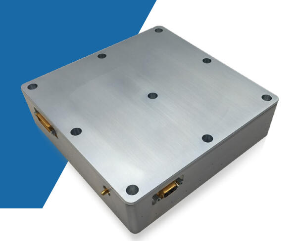
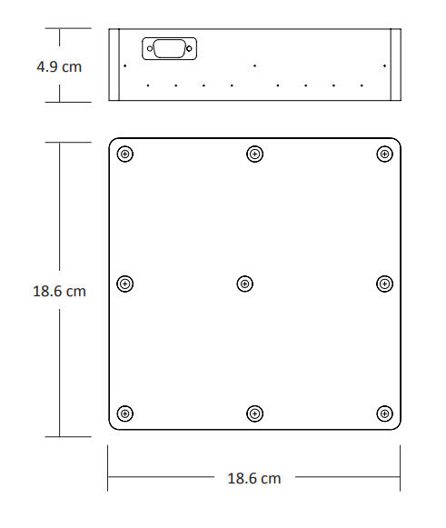
The HP-LCCE was designed to support a wide range of linear cryocoolers, from various manufacturers, at the nominal output power point of 200 W. It represents an FPGA based general purpose, radiation hardened platform for the control of a variety of devices types such as motors, actuators, solar power / battery charging systems, and optical bench thermal stabilization.I worked on the design of the housing and lid, as well as the external connector on the board. All parts were made in Solidworks and prototyped with the help of outside CNC machinists. The lid had to be designed to match the circuit board on the inside for ideal heat dissipation of hot components. I modeled the board using Circuitworks, and ran thermal simulations on the entire system with Solidworks Simulation. Vibration analysis was also ran to ensure the system met launch requirements.
Caltech Engineering/Design Capstone Project
This was a 6 month project that I worked on with three other people as part of our Caltech Engineering Design Capstone Project. The objective to make three remotely controlled robots to manipulate a soccer ball into a goal. They would be put to the test in a competition against other groups. We saw these robots from inception, to design, to CAD, to prototype, to semi-functional robot, to finished product. We also took third place in the competition!

Building the first robot.

Building the second robot.

First Protype!

Fixing the third robot.

Unwarping the wood.

Ready for the competition.
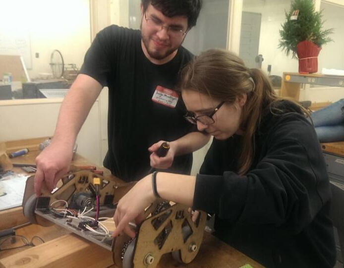
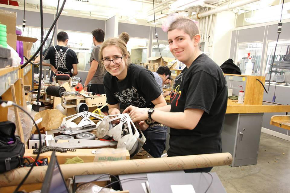
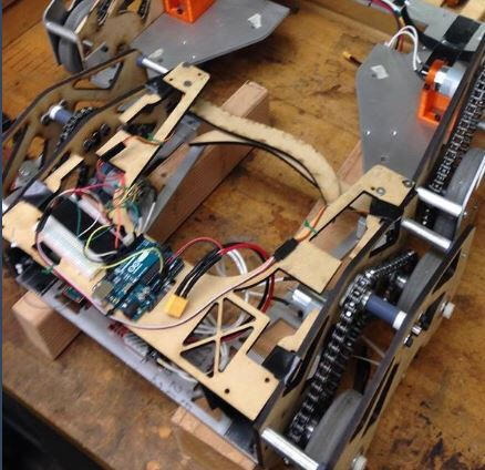
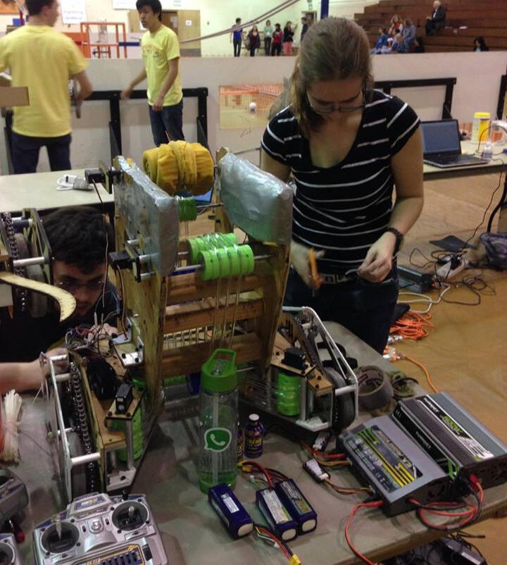
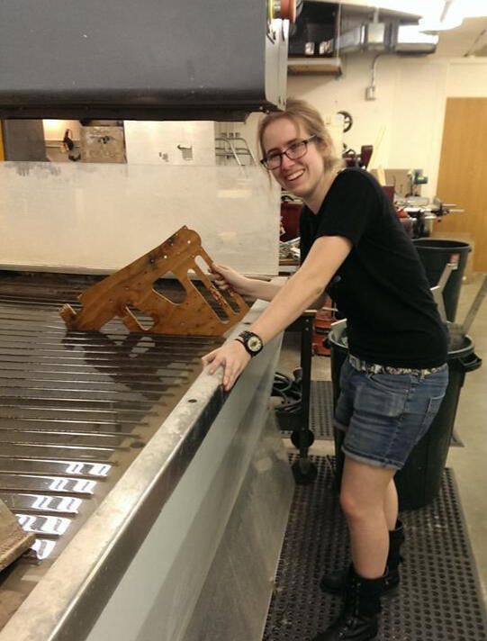
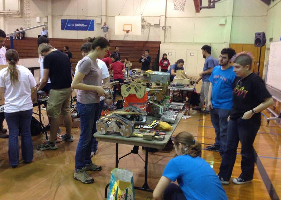
The first of the three robots we built was named Skipper. This bot took the longest time to make out of the three, because we spent a long time prototyping and modifying the design.First, we laser cut a test base plate and inner walls to determine if our bracketing system worked. When it did, we remade a base plate out of aluminum (since our initial MDF plate was far too weak). The next task was to make a functional drive train. We machined more sprockets than we could ultimately count (our sprockets were handmade because buying them was out of our budget), 3D printed motor mounts and spacers, and made standoffs. Eventually we managed to assemble these parts with our bought wheels, chain, and motors. Our motors didn’t come in until the day before the mobility demo (despite being ordered more than a month in advance), so there was a big rush for our first assembly. Our motors were attached to the necessary electronics to make it run, and after a few tries (most of which were followed by us troubleshooting the drive train) it worked!After the demo, we added claws to grab a soccer ball and keep it in Skipper’s possession. These claws were dubbed “The Skipper Flipper Grippers.” Other minor improvements were made (some electronics modifications, new Flipper Grippers, and a new top plate) for the soccer matches. Skipper preformed well in the matches of the final competition; the bot’s biggest drawback turned out to be the motors we chose - they started smoking in the second to last match. Thankfully, nothing caught fire, and I’m very pleased that none of the mechanical components (like the drive train) failed.The second robot we built was named Captain. Half of Captain was built exactly like Skipper, with an aluminum base plate and the same type of drive train. The only difference was that this robot was slightly bigger, in the hopes of bolstering our offense. The drive train worked perfectly, though we did run into the same issues with the motors as we did with Skipper. A big takeaway from this project was to test your electronics in the same circumstances as the final performance - in our case, we should have ran them as long and hard as we did during the competition.The other half of Captain was unique. The plywood walls and rollers within it were constructed to raise a ball and push it into a taller goal. The rollers were 3D printed and the walls were waterjet. We had an issue with the wooden walls warping during construction, so we dunked them in the bath of the waterjet and let them dry weighted down, which undid the warping.T Meanwhile, the polycord (which went around the rollers to grab and lift the ball) was cut and fused together. We added a foam roller at the top and additional padding during construction. Unfortunately, we ran out of time to properly test the rollers, and this part of the robot did not work entirely as planned. However, I learned a lot while constructing it, so I wouldn’t write it off as a total loss... but in hindsight, we should have cut our losses earlier and dedicated more time to the non-roller parts of the robot.The third and final robot we built wa named Ender. Ender was built just like Skipper, expect slightly bigger and made out of aluminum instead of the partially aluminum, partially MDF construction of skipper. This robot was the most reliable, as we had finally figured out what we were doing at this point. In one of our practice runs, Ender went over a bump and got some air, doing a 180 flip in the process, and getting no damage. (We learned very quickly not to drive it at max speed over bumps, to save the gym floor from scratches).This project was one of the highlights of my time at Caltech. It took half a year and no small amount of blood, sweat, and tears, but I'm very proud of what my team made together.
Nano-Tensegrity-Lattice Research Project
The main goal of this project was to design lattices made out of tensegrities at the nano-scale. Nanolattices had been made before. Tensegrities had been made before. But tensegrities had never been made at the nanoscale before. I figured out how to make one tensegrity at the nanoscale (the main challenge was figuring out the equivalent of bars and strings for tiny polymers), then figured out how to make a nanolattice of these tensegrities. These were the first Nano-Tensegrity Lattices ever made, and also the smallest thing I've ever worked on.

MATLAB Figure of 1 Tensegrity

MATLAB Figure of 1 Lattice

A printed Tensegrity

A printed Tensegrity Lattice
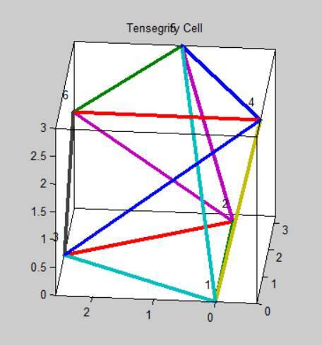
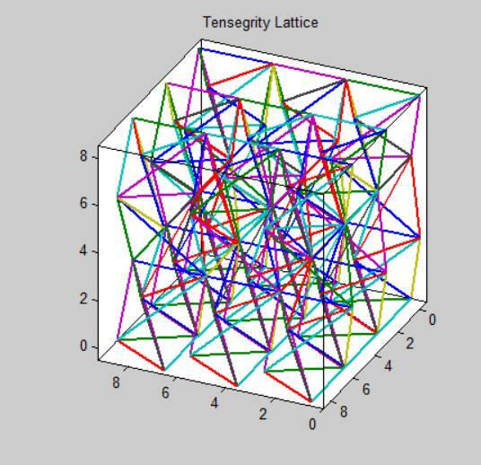
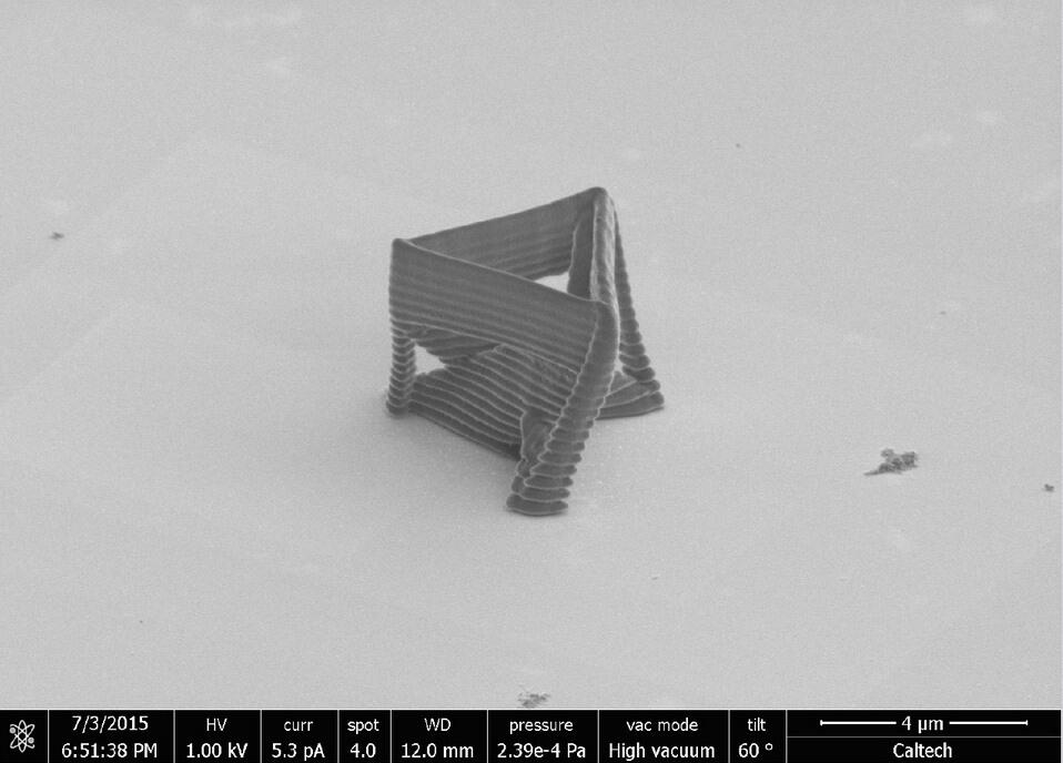
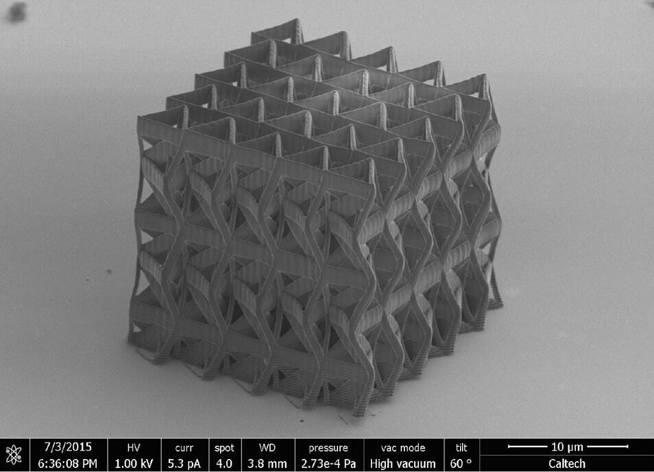
MATLAB was used to create a simple design of the tensegrities and generate the code that the nanofab machine used to make them with Two-Photon Lithography. It was important to generate models of these designs in MATLAB first, as using the Photon Lithography machine was expensive. The end result of these structures proved to be light, strong, and reliable.This project was a 10-week full time research project done at Caltech with the Greer Lab. The abstract to my paper that I wrote about this is below:Tensegrity systems are lightweight structures that exhibit a high weight-to-strength ratio due to an efficient distribution of mass and force among its structural elements. Literature exists on macroscopic tensegrity systems, but very little exists on the mechanical behavior of tensegrity structures at the nanoscale. We investigate a new class of structural metamaterials composed of tensegrity architecture, which have the potential to enhance mechanical properties and simultaneously take advantage of size effects at the nanoscale. Minimal, regular, tensegrity lattices made out of polymer were fabricated using two-photon lithography and various arrangements of the lattice unit cell were fabricated. Compression experiments were performed and the mechanical properties and deformation of these nano-tensegrities were studied.
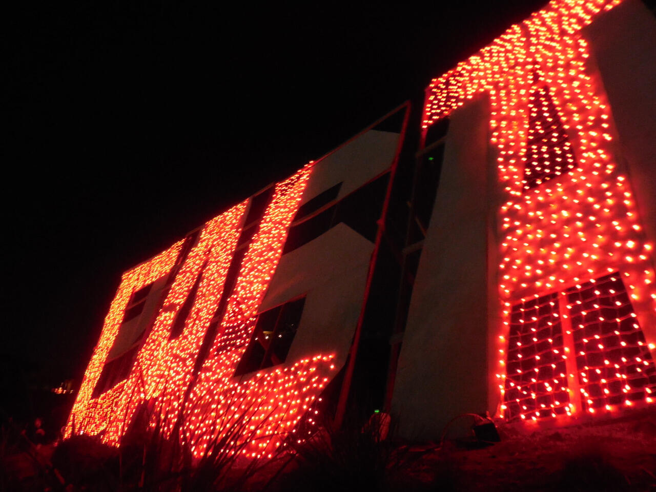
Caltech Sign Construction Project
The goal of this project was to create an 8 lettered PASADENA sign in the style of the famous HOLLYWOOD sign, and mount it above the Rose Bowl for a game. The sign would have net lights on it to spell out CALTECH, surprising attendees at the game. Each letter was 20 feet tall. Initial construction took place at Caltech, then the frames were transported to our location, where final assembly took place on top of a hill. I was part of this project from start to finish, and assisted in overseeing construction and planning transportation and assembly.

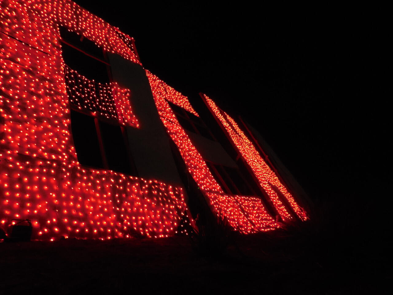
The sign at night...

... reading CALTECH!

Where it started.

Where it ended.

Front view of finished sign.

A tweet about our project!
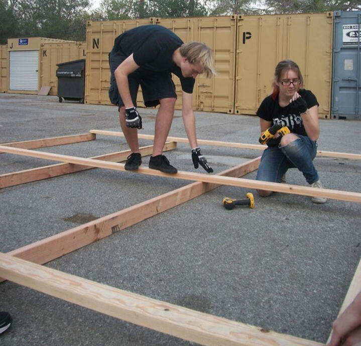
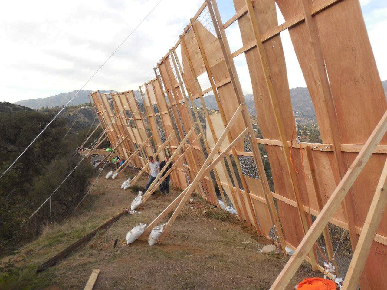
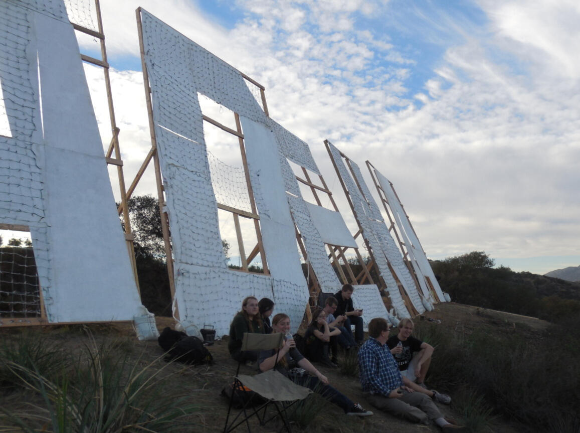
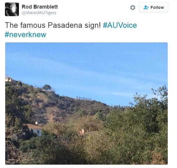
This started with a group of 10 students and ended up with half of the Caltech undergrad population helping.Some time ago, Caltech pulled off a prank on the Hollywood sign, turning it into a giant sign for Caltech. Since then, students have wanted to recreate this prank in some way, but the security around the sign is now much greater than it was before, making such endeavors fairly difficult.So the idea was had to build a giant Pasadena sign on the mountains overlooking the Rose Bowl in the days before a big game there, and during halftime at the game, turn on net lights on the sign to spell out Caltech - effectively pranking the sign.I joined the group working on the project just as construction started. The plan was to build 16 by 20 feet frames that could be propped up by a few people. I helped construct the first prototype frame out of 2x4s, and with only a few modifications, we got it working as planned. The biggest constraint was that we had to transport the partially assembled frames to the foot of the hill with a truck, then hoist the frames up the hill and finish their assembly on the top. In order to fit the frames into the truck, we determined that they had to be cut in half straight down the middle. Thankfully, we worked out a way we could quickly and easily repair the halved signs, so it ended up not being an issue.Once the frames were built, cut in half, and transported to the hill, we faced another big problem - how to get them up. There was a small trail that people could use to carry the smaller supplies up by hand, but the large frames weren’t going to fit along it (and nobody wanted to completely disassemble them). So we worked out a way of dragging them up the hill using ropes and harnesses. After many man hours, everything we needed to finish them was at the top of the hill. By this point, we had mass-emailed the Caltech undergrad population with a plea for help, and plenty of people volunteered to put in the labor of getting this massive piece of construction up a hill.On top of the hill, the frames were finished and hardboard was stapled to them to form the large letters. Net lights were then stapled to the hardboard, and lots of testing (and light-bulb replacement) happened. Eventually, the letters were ready to be pushed up.We got the letters standing early in the morning on the day of the game. Throughout the day, there were posts on Instagram and Twitter about the Pasadena sign. A smaller group of people (the ones that had been involved from the start) went back up that afternoon to get everything ready for the game. When it was finally halftime, we turned the lights on and the Pasadena sign turned into a Caltech one!It was all well and good for about 5 glorious minutes. Then, we heard one of the inverters (interfacing between a car battery and a letter’s lights) beeping and saw one of the letters go out. A few seconds later, this happened again with a different letter. And again and again, until all the letters were dark. We had one car battery powering each sign, and we knew they were fully charged, so we had no idea what was causing it. Upon turning the inverter back on, the letter would light up for a few seconds and then the beeping would start and it would turn off again. Later, we determined that the inverter did not handle the car battery’s charge dropping below completely full very well, but not knowing this was the problem at the time, we sent some people down the hill to get the batteries out of the cars we had driven there with. In the meantime, those of us still at the top ran around turning the letters on after they shut off each time. But not wanting a chaotically flashing Caltech sign, we started coordinating the letters to turn on and off in more sensible ways - turning them all on and off at once, then flashing Cal then Tech, then turning on one letter at a time in order. We were hoping that, to the people at the game below us, it would look perfectly intentional. Since the additional car batteries didn’t help, we ended up coordinating the letter flashing for the rest of the game.Despite the small setback from the electrical problems, the prank was a great success! It was a fantastic experience to see a pile of 2x4s, hardboard, and net lights turn into an amazing sign. Lots of people noticed our work, and I had a really fun time throughout the entire process.Pasadena Star News wrote a piece about this.